Basra Oil Company
Majnoon Oil Field
Gulf Water Treatment CO. LTD.
China Petroleum Engineering & Construction Corporation (CPECC)
KBR
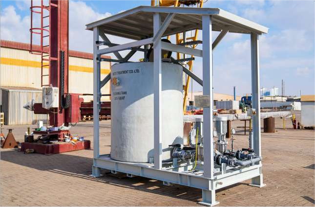
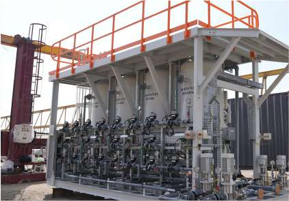
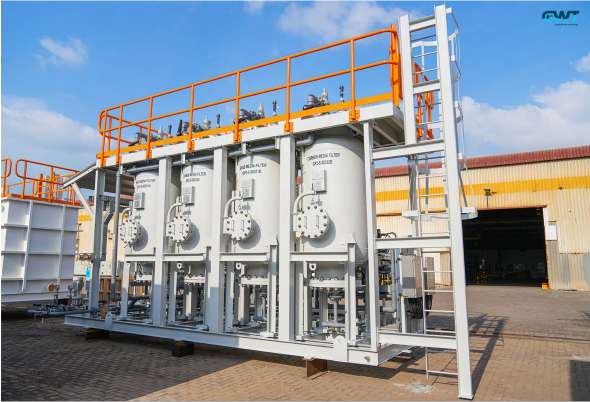
Coagulation and Sedimentation: Raw feed water is pumped to a coagulation tank for the removal of larger particles. The process uses tube settlers to enhance sedimentation efficiency.
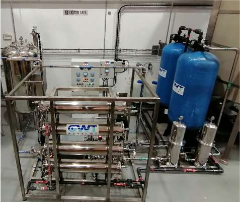
Multimedia Filters (MMF): Designed to remove suspended solids and reduce the Silt Density Index (SDI) of feed water, with backwashing utilizing RO reject water.
High-Pressure Pumps: Designed for optimal feed flow and pressure to maximize recovery rates.
RO Membrane Technology: Polyamide composite membranes provide 99.8% salt rejection and produce water with <500 mg/L salinity.
Two-Stage RO Configuration: Improves recovery rates and permeate water quality.
UV Sterilization Unit: Provides effective disinfection, ensuring microbial safety in treated water.
Chemical Dosing Systems: Includes dosing of anti-scalants, sodium bisulfite (SMBS), and pH adjustment for process optimization.
SS316 for high-pressure sections, UPVC for drains, and CPVC for chemical dosing lines
Three 40-ft High-Cube Containers: All components are pre-assembled, including pre-treatment, RO, and chemical dosing systems.
Thermal insulation, air conditioning, and exhaust fans are provided to ensure operational stability.
PLC-based controls with real-time monitoring of pH, conductivity, and flow.
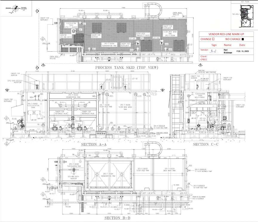
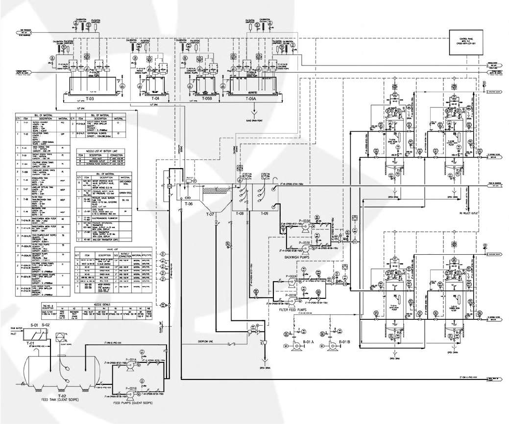
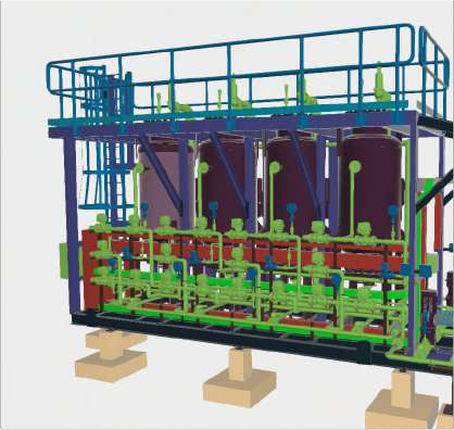
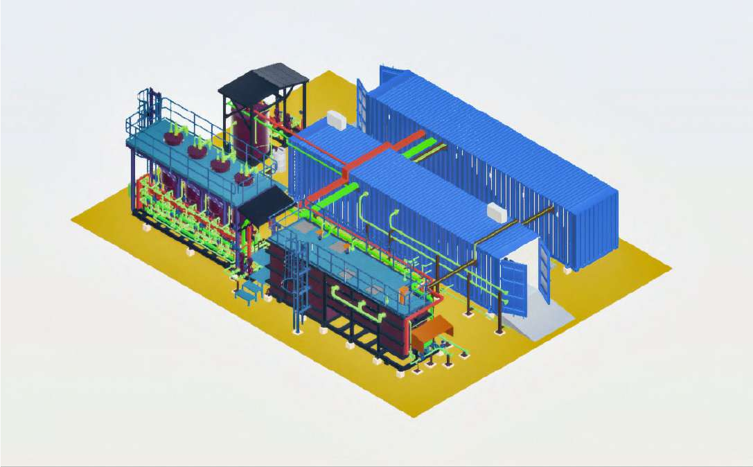
Detailed schematic of the treatment process
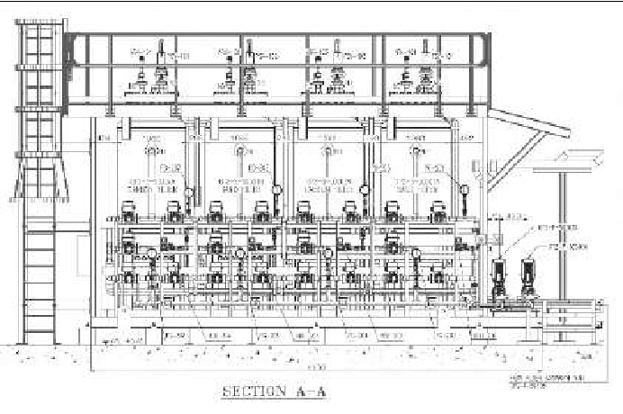
Layout and spatial organization of components
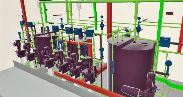
Interactive 3D representation of the plant